Why measure step heights?
The inspection of step height plays an important role in quality inspection within surface metrology. For this reason, many technical drawings contain tolerance specifications for height dimensions, for example for shoulders, grooves and bores. If the specifications for step height are violated, disadvantageous gap dimensions occur or two component surfaces come into unintentional contact. This can lead to leakage at sealing surfaces, interrupted current flow at electrical contacts or increased frictional resistance and wear. In addition, the step height measurement can also be used to optimize build-up or ablation manufacturing processes; both the thickness of non-transparent layers can be determined and the material removal e. g. by laser pulses can be checked.
How to calculate step-height?
Step height measurement is not a standardized procedure unlike other frequently tested characteristics such as flatness, parallelism or roughness evaluation. There are several calculation methods to choose from, the results of which may differ due to non-ideal geometries and measurement conditions:
- Method 1:
The step height is determined as the vertical distance between the center of gravities of two surfaces - Method 2:
The step height is determined as the vertical distance between the (extrapolated) regression plane of one measurement surface and the center of gravity of a second surface.

Method 1 referring to gravity centers shows great simplicity, but also faces high sensitivity regarding the tilt of the measurement object. Method 2 overcomes this disadvantage and is therefore the preferred way of determining step height. Because the choice of the reference plane has an influence, it must be marked in the technical drawing.
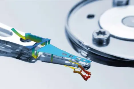
How to measure surface flatness & step height
– TopMap optical 3D surface characterization
Differences of profile-based and areal-based step height measurement
Step heights can be checked by mechanically touching the respective surfaces with a probe. With the help of coordinate measuring machines, individual measuring points are often recorded and used for the calculation. During scanning, the probe is moved over the surface in a contacting manner. The higher measuring point density is offset by a greater uncertainty of the measured values. Optical sensors allow a non-contact profiling, reaching evendeeply recessed surfaces that might not be accessible for a mechanical probe.
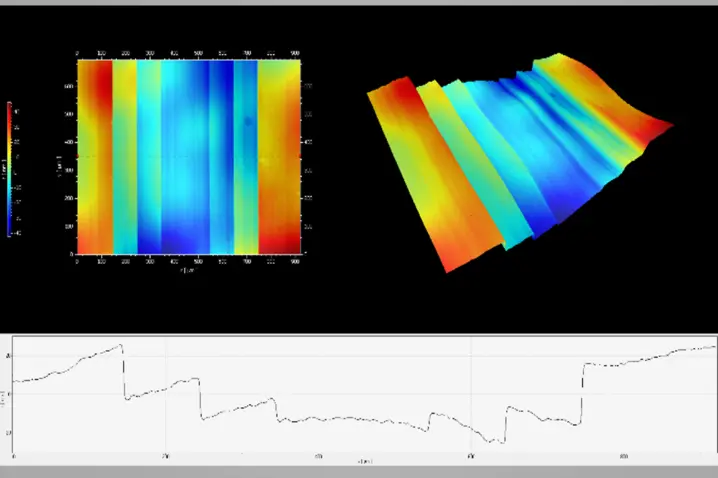
Both methods - tactile probers and optical line profilers - only use local measurement data, i. e. at specific points or along a profile. Using this for a close-meshed scanning of the surface is time-consuming. However, a quick scan or even random testing involves the risk of missing relevant deformations for further evaluations.
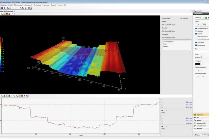
Areal step-height measurement using Coherence Scanning Interferometry (CSI)
White-light interferometers use coherence scanning technology to determine step heights precisely, without contact, and even at measurement positions that are difficult to access with a mechanical probe. Millions of measuring points in a single shot provide a complete 3D image of the surface, so that the shape of the relevant measuring surfaces can also be taken into account. The areal step height measurement promises reliable measurement results for efficient quality inspection. In addition to step height, the measurement also provides detailed information on flatness and orientation of the two surfaces, allowing to analyze the cause of quality problems. Large working distances, collision-free handling and robust measuring technology make the white-light interferometer the measuring instrument of choice both for quality control at production level and for 100% inspection.
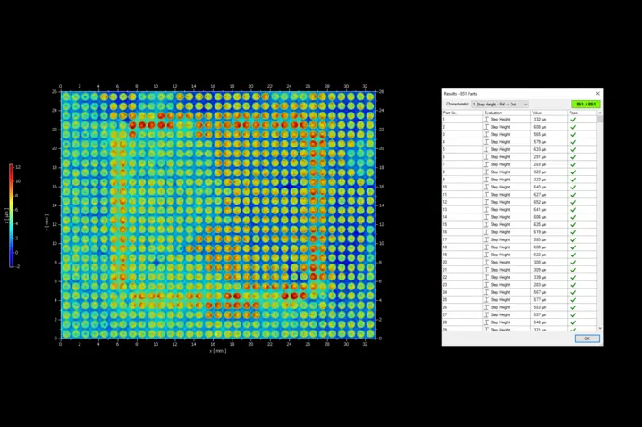
Automated step height inspection and pass-fail analysis
In order to ensure that each component meets the step height specification, a measurement and evaluation routine can be implemented for 100% quality control. With recipes, the TMS software offers the ideal tool to carry out the entire inspection process completely automatically with just one mouse click. Thanks to intelligent software solutions, it is even possible to dispense with sample holder in many cases. Based on defined tolerances, you receive a good/bad evaluation, so that reject parts can be sorted out manually or mechanically by communication of the measurement device with PLC/ process control.
Your WLI options for step height measurement
Pro.Surf+
Multi-sensor optical profiler combining large-area form measurement with integrated roughness analysis. Pro.Surf+ delivers fast, traceable form and roughness results in one production-ready system.
Pro.Surf
Pro.Surf is a telecentric WLI/CSI system for fast, non-contact form and topography measurement. Due to a large FoV it is perfect for wider parts and trays - down to nm scale.
Metro.Lab
Metro.Lab is a compact, wide-area surface profiler. It combines high measurement performance with a small footprint—ideal for space or budget conscious applications that still require reliable 3D surface data.
Choose the right surface profiler with confidence—benefit from our "try before buy" approach.

Further surface parameters
Discuss your demands with our experts
Let’s start with a short discussion about your parts, tolerances, and workflow—and, if useful, we can add a feasibility study, PolyMeasure (contract measurements), or a PolyRent trial as optional next steps.