Definition of modal analysis
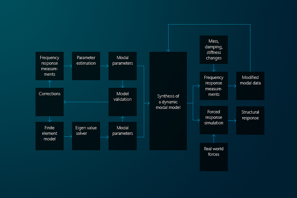
Modal analysis is the process of finding the inherent natural vibration properties of a structure. If these are known, all complicated vibrations that the structure can undergo as a response to a certain excitation, can be expressed as a superposition of these natural vibration states. Therefore, if the natural vibration states are known, much of the vibration behavior of a structure can be predicted. A natural vibration state is defined by its mode shape, its natural frequency and the associated damping.
Vibration modes of a structure can be either purely simulated, e.g. from Finite Element (FE) Models or can be derived out of physical measurement results by fitting a mathematical model to these results. This latter process is called experimental modal analysis.
Get in touch with our experts
Get in touch with our experts
How can we help you?
Experimental modal analysis and modal testing
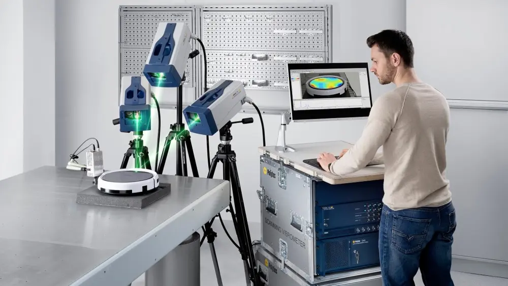
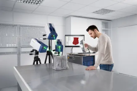
Modal analysis is a method to describe a vibrating structure in terms of its natural characteristics which are the frequency, damping and mode shapes – its dynamic properties. A standard setup for experimental modal testing requires sensor technology (force transducers, accelerometers, cameras or non-contact laser vibrometers), data acquisition and a computer for monitoring and analyzing the measurement data (DAQ). Without using a rigorous mathematical treatment, the linked whitepaper introduces some basic concepts about structural vibration and mathematical approaches for solving structural dynamics issues. Please sign up for downloading the free whitepaper.
How do you determine natural frequencies for modal analysis?
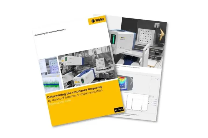
In this application note, learn how Eigenfrequencies and vibration modes of components can be determined quickly, precisely, and without contact using state-of-the-art laser Doppler vibrometry and suitable excitation methods. Automatic modal hammer or shaker are discussed for enabling reliable analysis of the dynamic properties.
Applications of experimental modal analysis
During an experimental modal test, first the vibration response of a structure is measured over frequency. The excitation should be spectrally broad to excite all relevant natural frequencies. Typically, the excitation spectrum is acquired as well, so that transfer function's (FRFs) response-input force can be recorded. The setup should be well defined to avoid any unwanted influences from the environment or the excitation process itself. A typical setup could be attachment of the structure to some soft rubber strings or putting it onto soft foam to decouple it from the environment and to excite it with e.g. a modal hammer.
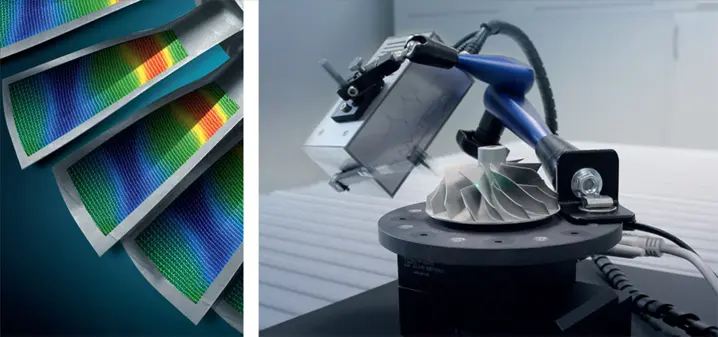
Next, the measured FRFs are curve fitted to a mathematical model involving the inherent modes of the structure under test. The result of this process are the natural frequencies, the damping and the mode shapes of the structure. These modes reveal valuable insights for any engineer and developer, e.g. for simulation in an early stage when designing new products or optimizing the design e.g. with increased lightweight constructions in engineering and construction. Examples of modal analysis typically include entire car-bodies, a wide range of precision components in automotive, aerospace and mechanical engineering, but also cover small parts in microtechnology.

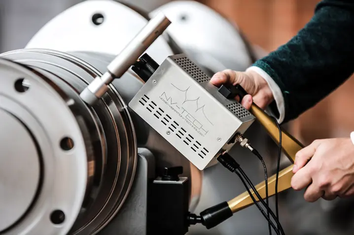
Measurements using broadband piezoelectric excitation
The following article compares various forms of force excitation in order to determine the transfer admittances of mechanical systems using a gear wheel as an example. The objective is to analyze and assess the acoustic properties of technical structures, e.g. the drive train of an electric vehicle, in the higher frequency range.
Experimental modal test with laser vibrometers
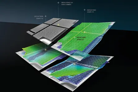
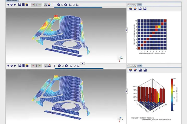
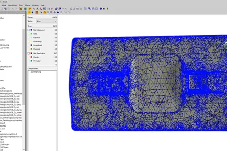
The validation of simulation models is an important application area of laser vibrometers. To do this, the geometric data from a finite element mesh is loaded into the software of the measurement system and brought into alignment with the real object using an integrated alignment process.
Boundary conditions, measurement inaccuracy, and repeatability
MAN Energy Solutions offers a comprehensive engine portfolio, propeller, and stern equipment and turbochargers for the maritime sector. Reliability is an essential aspect of our sector and especially vital on ships. During the development phase, simulation models are validated and optimized using modal tests, and examined until the components are released for series production.
On self-supporting and self-aligning compact shakers
Artificial excitation is the basis for various noise and vibration techniques, from experimental modal analysis, over transfer path analysis, load identification, simulation model correlation, hybrid modelling etc. Structural excitation is possible by various means, from manual impact hammers over automated hammers, externally supported shakers to self-supporting shakers.
Experimental modal analysis of lightweight structures

No budget? Just measure.
Whether you need contract measurements, equipment rental, or leasing, our scalable services deliver precise data—without the overhead of major investments. Ideal for short-term projects, occasional use, or limited budgets.
With PolyFlex you get results without compromising timelines or budgets.
Excitation in experimental modal analysis
For vibration measurement and experimental modal testing, the underlying test structure needs to vibrate. Some test structures vibrate by themselves (motors or fans) and others need external excitation. For the first group operational modal analysis can be used to some extent, the second group is the typical subject of experimental modal testing. For such induced excitation in experimental modal analysis, there are different means. Typical excitation techniques in modal testing include excitation by shakers, broadband noise excitation by a loudspeaker or dedicated manual or automatic modal hammers.
Some popular excitation signals for experimental modal analysis:
SIMO vs MIMO modal testing approach
The standard test is a single-input multiple output SIMO test. One excitation source and multiple response channels either with multiple acceleration sensors or in the case of a Scanning Laser Doppler vibrometer (SLDV) with a laser beam scanned over the surface is the most common test setup. The results can be directly analyzed and fed into a curve fitting software to extract the individual modes.MIMO – multiple-input multiple-output – setups are applied with highly damped larger structures or in cases where not all modes can be excited with one location of excitation like for symmetric structures, e.g. brake disks.
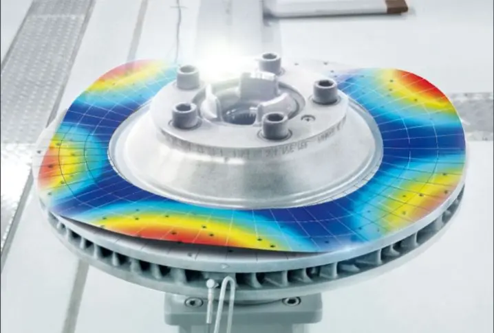
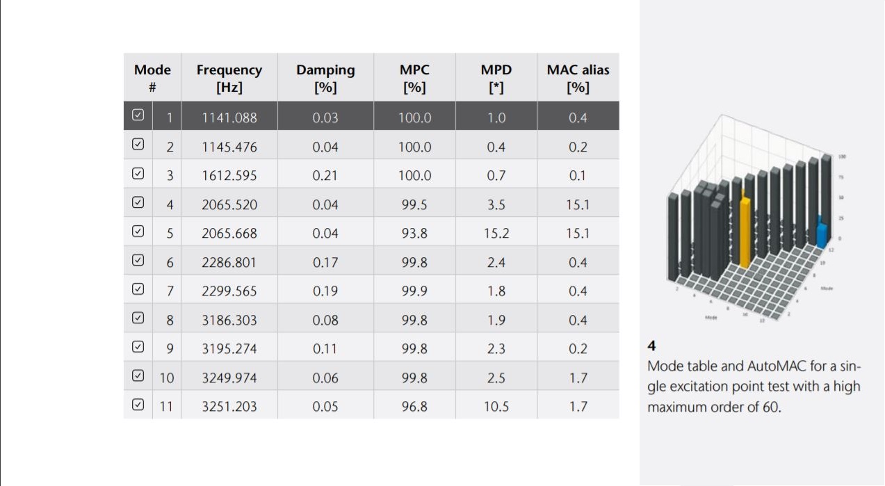
Modal testing of structures with closely coupled modes is a very frequent task. Structures often have modes that have almost the same resonant frequency. For example, a plate’s specific bending mode might occur at almost the same frequency as its torsion mode. This “accidental” frequency degeneracy is common among more complex geometries and structures.
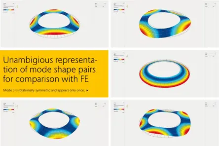
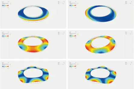
On the other hand, when a structure is planned to be highly symmetric, the coupled modes are expected “by design.” In finite element (FE) simulations, all of these modes appear separately. However, in real world testing, extracting the modes from measurement data can be challenging. This application note introduces a novel approach to separate closely spaced modes with MIMO testing (multiple input, multiple output) using a 3D scanning laser vibrometer and two automated modal hammers. Sign up for reading the full paper.
Experimental modal analysis (EMA) software
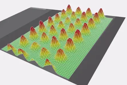
As a result of the experimental modal test the operational deflection shapes as answers to this special modal test excitation are available. To compare these results with the calculated results from a numeric modal analysis based on a FE model a second step called curve fitting is required. In the pure measurement results, the modes are potentially still coupled. The dynamic behavior of a mechanical system can be described as the superposition of the Eigen-modes, one mode being considered as a single degree of freedom (SDOF). In curve fitting the SDOF results are extracted with various methods, typically based on single value decomposition (SVD).
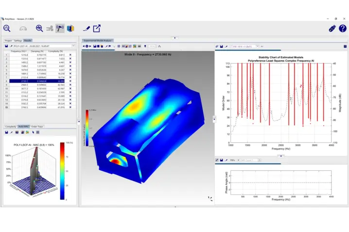
Experimental modal analysis software packages like PolyWave allow for curve fitting and the comparison of the EMA test results with the FEA results in MAC analysis. The findings like damping values, Eigen-frequencies and Eigen-vectors are fed back into the model to update the FE model parameters.
Measurement solutions for experimental modal analysis
For further information, find these additional sites and learn about Polytec solutions for importing, measuring, comparing, evaluating, post-processing and documenting any modal test data.
- How does the non-contact technology of laser Doppler vibrometry work?
- How to perform 1D single-point measurements or when to scan entire sample surfaces, maybe even in 3D?
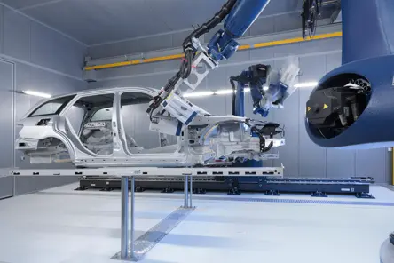
For complex shaped and larger structures, automated testing with robotics can significantly reduce testing time and cost. Polytec operates several structural test centers around the globe – in Waldbronn Germany, Plymouth, MI USA and Yokohama Japan for measurements as a service. Contact Polytec for individual modal analysis and modal testing projects.
Further applications

Talk to our experts
Our experts are ready to support your projects with tailored measurement solutions or support you in measuring what matters—get in touch with us today.
Related products
VibroScan QTec Xtra
VibroScan QTec Xtra measures vibrations in a new way - without contact, full-field and with unprecedented precision. With its groundbreaking multi-path interferometry, QTec® sets new standards in terms of optical sensitivity and interference immunity. The Xtra, based on an infrared (SWIR) laser is characterized by the highest optical sensitivity to guarantee highly accurate measurements even on demanding technical surfaces. VibroScan QTec Xtra ensures maximum portability through integrated data acquisition and signal generator up to 32 MHz.
VibroScan QTec Xtra 3D
VibroScan QTec Xtra 3D measures vibrations triaxially in a new way - without contact, full-field and with unprecedented precision. With its groundbreaking multi-path interferometry, QTec® sets new standards in terms of optical sensitivity and interference immunity. The Xtra, based on an infrared (SWIR) laser is characterized by the highest optical sensitivity to guarantee highly accurate measurements even on demanding technical surfaces. VibroScan QTec Xtra 3D ensures maximum portability through integrated data acquisition and signal generator up to 32 MHz.
RoboVib®
By combining a 3D scanning vibrometer and an industrial robot, RoboVib® forms an automated test station for measuring everything from complex components to complete vehicle bodies. Reduce testing time and expenses as well as time to market significantly in experimental modal analysis. Conduct comprehensive 360° testing of a vehicle body, for example, within only one-two days and overnight instead of weeks of preparation with conventional test setups.
MSA-600 Micro System Analyzer
The all-in-one optical measurement solution for static and dynamic 3D characterization of MEMS and microstructures- now for up to 8 GHz! The MSA-600 enhances microsystem development and quality inspections - also allowing testing on wafer-level when integrated into commercially available probe stations.
Measurement service & rentals
Our engineering services cover a wide range of applications, either onsite or in our laboratories. Ask for our PolyXperts, rent cutting edge laser measurement equipment and benefit from individual support for your projects. Our experienced application engineers are pleased to help, measure and test for you. For comprehensive studies, rent the RoboVib® Structural Test Station