When the circuit board becomes audible
Whining or humming from power supplies, notebooks or mobile devices can originate from electrically excited capacitors and their coupling to the printed circuit board (PCB). This effect is known as “singing capacitors.” A typical case involves multilayer ceramic capacitors (MLCCs).
Class 2 MLCCs with a ferroelectric dielectric are particularly relevant. Under electrical excitation, for example from the voltage ripple, their ceramic can deform through inverse piezoelectric and electrostrictive effects. Which share dominates depends, among other things, on the material and the DC bias voltage.
Terminals and solder joints transfer the motion to the PCB. Its bending vibrations can then radiate audible sound, and any resonances that occur can amplify the sound radiation. Film capacitors can also cause noise, for example DC link capacitors in electric drives that are mechanically excited by voltage ripple.
With Polytec laser Doppler vibrometers, you characterize such noise-generating vibrations non-contact and with spatial resolution – whether directly on the component, on the surrounding PCB or on other adjacent structures. This gives you a basis for optimizing component selection, placement and PCB design in a targeted way.
Typical questions in development
A metrological investigation clarifies where the excitation acts, how the assembly responds and which change affects the relevant vibration. Typical questions include:
- Which capacitors and adjacent structures vibrate at the conspicuous frequencies?
- How are excitation and mechanical vibration response related?
- How are component motion and the structural response of the PCB related spatially?
- How do component selection, mounting, layout or drive signal change the structural response?
- How well does the simulation describe the measured amplitudes and deflection shapes?
If a microphone is used instead of a vibrometer, the exact spatial reference is lost. A microphone captures the sound pressure at the measurement location, where contributions from several radiating areas can overlap. For a structural root cause analysis, it therefore lacks a direct spatial reference.
What laser vibrometry contributes
Non-contact measurement. Unlike an accelerometer, the laser beam adds no mass to the test object. Even small, lightweight components can therefore be examined without any mass loading.
Targeted spatial reference. You place the measurement point directly on a capacitor, the PCB or a housing area. With suitable optics, the laser spot can be considerably smaller than the component, so that neighboring components can be examined separately.
Spatially resolved analysis. A scanning vibrometer measures the points of a measurement grid one after the other and displays amplitude distributions and the phase relationships between the measurement points. This shows how the components and the PCB vibrate relative to each other.
Visualizing vibrations. The software animates the measured deflection shapes. This makes it easier to align electronics development, acoustics and simulation.
Choosing the right optics. Depending on component size and the question at hand, standard, close-up or microscope optics are used. A microscope extension is not mandatory for an overall view of a PCB.
Examining capacitors and PCB together
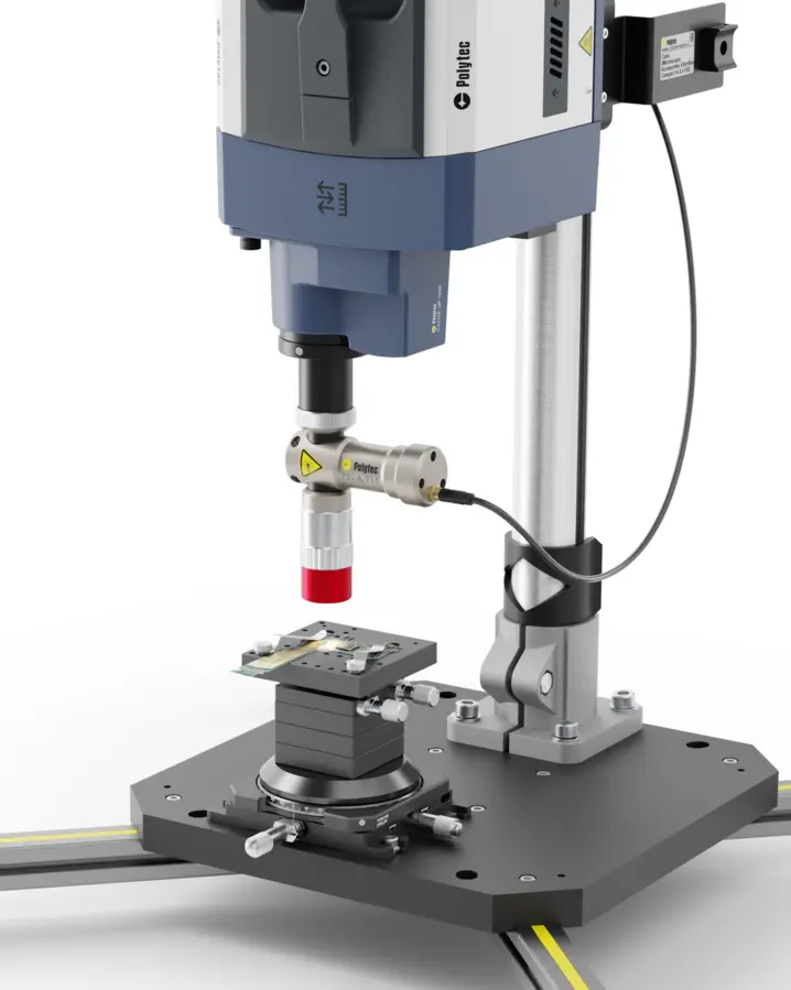
An application example from the Polytec Magazine shows a populated PCB with a group of SMD capacitors (surface-mounted devices). The measurement was performed with a PSV Scanning Vibrometer in a vertical setup. The figures show the spatial distribution qualitatively; frequencies and absolute values are not stated here.
Measurement setup
The sensor head is positioned vertically above the test object. Scanning mirrors direct the laser beam successively to the points of a measurement grid that covers both the PCB and the components. This arrangement is suitable for small, flat assemblies.
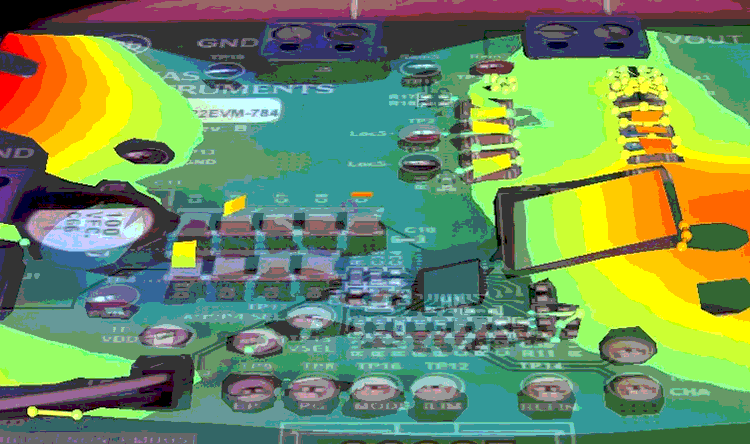
Capacitor group in the vibration image
The measurement grid is overlaid on the camera image of the PCB and shows the deflection at each measurement point. The group of SMD capacitors examined in the article is highlighted. This allows the motion to be assigned directly to individual components and areas of the PCB.
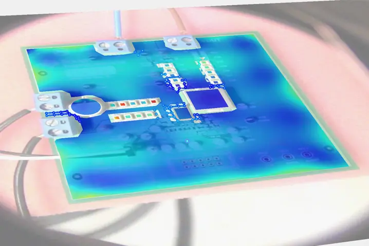
Spatial distribution of RMS vibration values
The full-field scan shows the root mean square (RMS) values of the vibration across the entire PCB. Individual components in the capacitor rows stand out in color from their surroundings, while large parts of the board show lower values.
Only this overall view reveals whether an anomaly remains localized or spreads across the PCB.
Related products
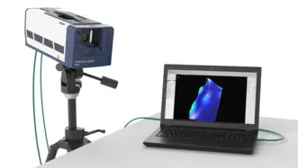
VibroScan QTec Xtra
VibroScan QTec Xtra 以一种全新的方式测量振动——非接触式、全场测量,且精度前所未有。凭借其突破性的多路径干涉技术,QTec® 在光学灵敏度和抗干扰能力方面树立了新标杆。Xtra基于红外(SWIR)激光器,具有极高的光学灵敏度,即使在技术要求极高的表面上也能保证高精度测量。VibroScan QTec Xtra 通过集成数据采集和最高32 MHz的信号发生器,确保了极高的便携性。
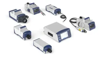
VibroFlex
Polytec 推出的模块化激光测振仪VibroFlex ,凭借最高支持32 MHz的模块化传感器解决方案,在光学振动测量领域展现出卓越的灵活性,可灵活适应您的需求:添加显微镜物镜以观察微小结构,或从安全距离测量大型样品(如机械设备或电机)。在研发和产品开发中探索声学与振动现象,以加快产品上市速度,或将其用于可靠的在线检测。 了解专利的多路径干涉技术QTec® 如何提供始终稳定的信号电平,信噪比(SNR)提升 20 dB,从而在无需后处理的情况下获得更快、更清晰的结果。
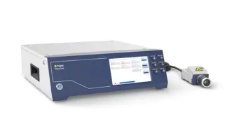
VibroOne+
VibroOne® 多普勒激光测振仪是一款适用于最高 3 MHz 频率范围的非接触式振动测量的一体化解决方案。它专为空间受限的安装环境而设计,无论是在研究实验室、条件严苛的生产环境中,还是用于对微结构或生物医学探针上的微小细节进行非接触式分析,均能胜任。可选配的内置 HD+ 摄像头有助于精确定位激光,并提供完整的测试记录。