
When the circuit board becomes audible
Whining or humming from power supplies, notebooks or mobile devices can originate from electrically excited capacitors and their coupling to the printed circuit board (PCB). This effect is known as “singing capacitors.” A typical case involves multilayer ceramic capacitors (MLCCs).
Class 2 MLCCs with a ferroelectric dielectric are particularly relevant. Under electrical excitation, for example from the voltage ripple, their ceramic can deform through inverse piezoelectric and electrostrictive effects. Which share dominates depends, among other things, on the material and the DC bias voltage.
Terminals and solder joints transfer the motion to the PCB. Its bending vibrations can then radiate audible sound, and any resonances that occur can amplify the sound radiation. Film capacitors can also cause noise, for example DC link capacitors in electric drives that are mechanically excited by voltage ripple.
With Polytec laser Doppler vibrometers, you characterize such noise-generating vibrations non-contact and with spatial resolution – whether directly on the component, on the surrounding PCB or on other adjacent structures. This gives you a basis for optimizing component selection, placement and PCB design in a targeted way.
Typical questions in development
A metrological investigation clarifies where the excitation acts, how the assembly responds and which change affects the relevant vibration. Typical questions include:
- Which capacitors and adjacent structures vibrate at the conspicuous frequencies?
- How are excitation and mechanical vibration response related?
- How are component motion and the structural response of the PCB related spatially?
- How do component selection, mounting, layout or drive signal change the structural response?
- How well does the simulation describe the measured amplitudes and deflection shapes?
If a microphone is used instead of a vibrometer, the exact spatial reference is lost. A microphone captures the sound pressure at the measurement location, where contributions from several radiating areas can overlap. For a structural root cause analysis, it therefore lacks a direct spatial reference.
What laser vibrometry contributes
Non-contact measurement. Unlike an accelerometer, the laser beam adds no mass to the test object. Even small, lightweight components can therefore be examined without any mass loading.
Targeted spatial reference. You place the measurement point directly on a capacitor, the PCB or a housing area. With suitable optics, the laser spot can be considerably smaller than the component, so that neighboring components can be examined separately.
Spatially resolved analysis. A scanning vibrometer measures the points of a measurement grid one after the other and displays amplitude distributions and the phase relationships between the measurement points. This shows how the components and the PCB vibrate relative to each other.
Visualizing vibrations. The software animates the measured deflection shapes. This makes it easier to align electronics development, acoustics and simulation.
Choosing the right optics. Depending on component size and the question at hand, standard, close-up or microscope optics are used. A microscope extension is not mandatory for an overall view of a PCB.
Examining capacitors and PCB together
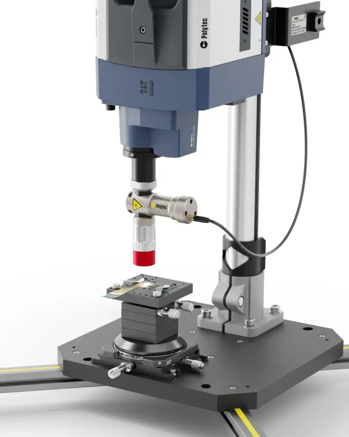
An application example from the Polytec Magazine shows a populated PCB with a group of SMD capacitors (surface-mounted devices). The measurement was performed with a PSV Scanning Vibrometer in a vertical setup. The figures show the spatial distribution qualitatively; frequencies and absolute values are not stated here.
Measurement setup
The sensor head is positioned vertically above the test object. Scanning mirrors direct the laser beam successively to the points of a measurement grid that covers both the PCB and the components. This arrangement is suitable for small, flat assemblies.
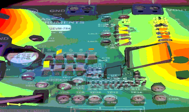
Capacitor group in the vibration image
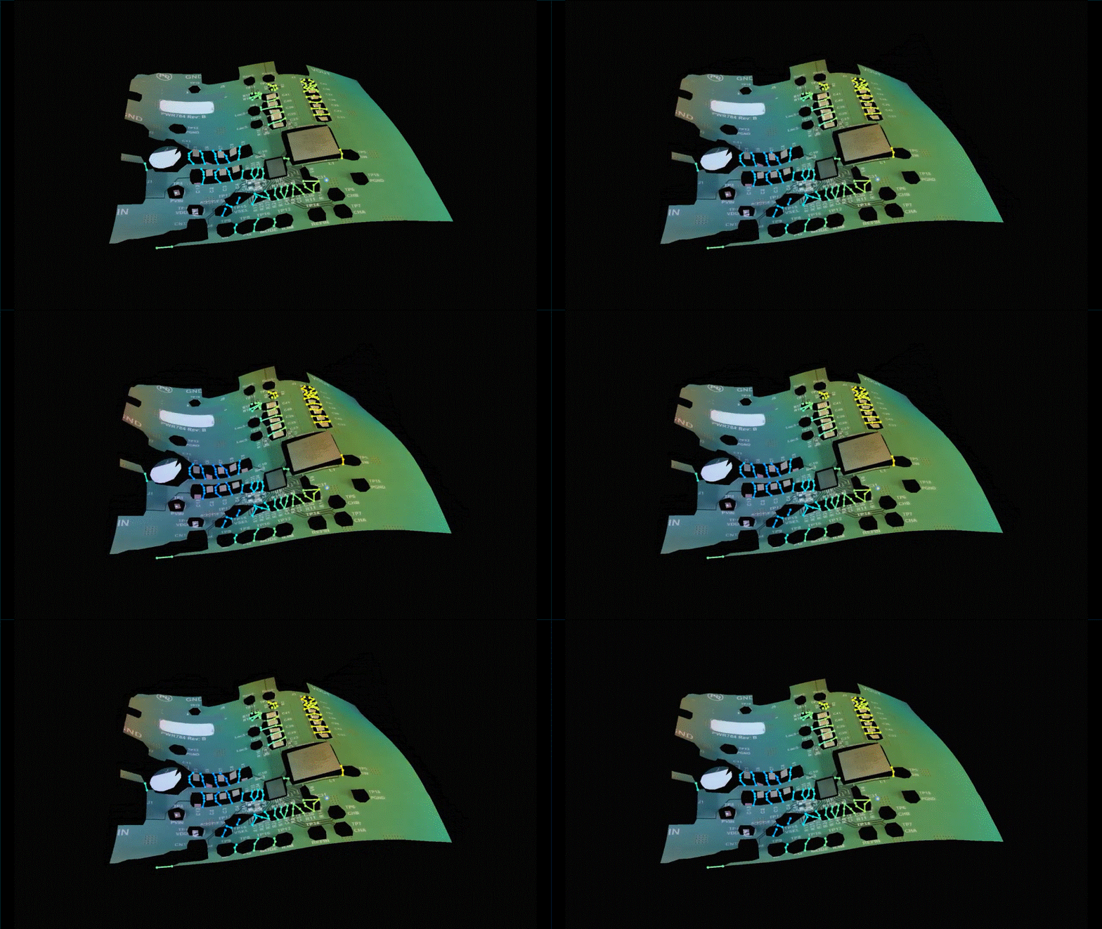
The measurement grid is overlaid on the camera image of the PCB and shows the deflection at each measurement point. The group of SMD capacitors examined in the article is highlighted. This allows the motion to be assigned directly to individual components and areas of the PCB.
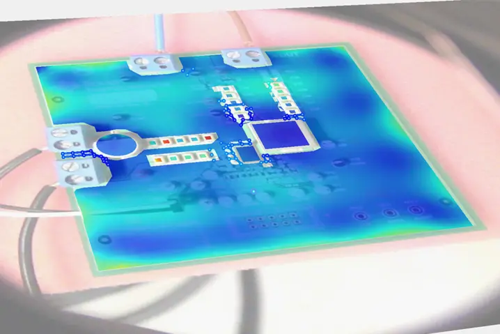
Spatial distribution of RMS vibration values
The full-field scan shows the root mean square (RMS) values of the vibration across the entire PCB. Individual components in the capacitor rows stand out in color from their surroundings, while large parts of the board show lower values.
Only this overall view reveals whether an anomaly remains localized or spreads across the PCB.
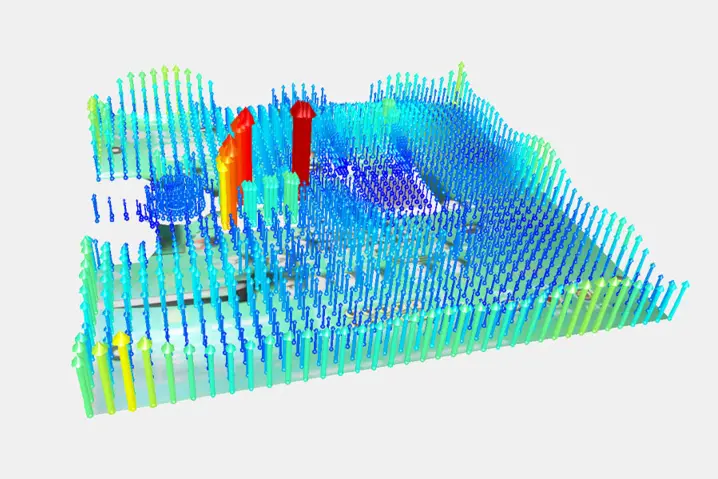
Identifying conspicuous areas
In the three-dimensional display, the length and color of the arrows represent the RMS values at the measurement points. A few points in the area of the capacitors stand out clearly.
Such a local maximum is an important indication, but not yet proof of the noise source. Comparing it with the electrical excitation and carrying out targeted comparative measurements help narrow down the cause.
Operating deflection shape as an animation
The animation shows the measured operating deflection shape (ODS) of the PCB. It visualizes how the capacitor group and the surrounding PCB move together.
An operating deflection shape describes the behavior under the respective excitation. It is not automatically a mode shape; modal parameters require a suitable modal analysis.
Related products
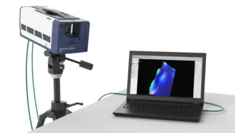
VibroScan QTec Xtra
VibroScan QTec Xtra misst Schwingungen auf eine neue Art – berührungslos, flächenhaft und mit ungekannter Präzision. Mit seiner bahnbrechenden Mehrkanal-Interferometrie setzt QTec® neue Maßstäbe in Sachen optischer Empfindlichkeit und Störsicherheit. Das Xtra basierend auf einem infraroten (SWIR) Laser zeichnet sich durch höchste optische Empfindlichkeit aus, um hochgenaue Messungen selbst auf anspruchsvollen technischen Oberflächen zu garantieren. VibroScan QTec Xtra gewährleistet maximale Portabilität durch integrierte Datenerfassung und Signalgenerator bis 32 MHz.
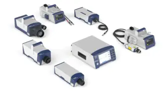
VibroFlex
VibroFlex steht für die Flexibilität der optischen Schwingungsmessung: Analysieren Sie kleinste Strukturen mit Mikroskopobjektiven oder messen Sie an großen, komplexen Objekten wie z. B. Maschinen oder Motoren auch aus sicherer Entfernung. Lösen Sie schwingungstechnische und akustische Fragestellungen in Forschung und Produktentwicklung für eine kurze Time-to-Market oder nutzen Sie VibroFlex für die zuverlässige Qualitätskontrolle in Ihrer Fertigung. Erfahren Sie wie die patentierte Mehrkanal-Interferometrie QTec® mit stets stabilem Signal, 20 dB besserem Signal-Rausch-Verhältnis für klare Ergebnisse ohne Post-Processing sorgt.
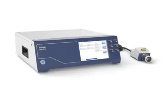
VibroOne+
VibroOne® ist das kompakte all-in-one Laser-Doppler Vibrometer von Polytec zur berührungsfreien und hochpräzisen Schwingungsmessung bis zu 3 MHz. Es ist speziell für den Einsatz in engen Messaufbauten im Messlabor, in Prüfständen und in der Produktionsumgebung sowie für die Analyse von Mikrostrukturen und biomedizinischen Proben konzipiert – mit optionaler integrierter HD+ Kamera für ein präzises Ausrichten und eine einfache Dokumentation.


Unsere Experten befragen
Unsere Experten unterstützen Ihre Projekte mit maßgeschneiderten Messlösungen – oder helfen Ihnen dabei, das zu messen, was wirklich zählt. Kontaktieren Sie uns noch heute!