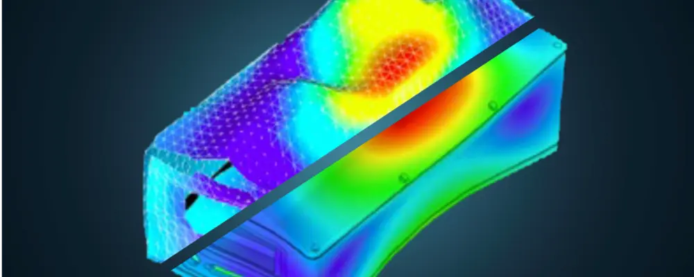
Finite Element model validation - comparing simulation model & modal test data
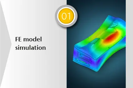
Finite Element (FE) models can greatly reduce development time and cost, as it can be done on a computer with less prototyping. But the main concern is that these FE models have to predict the behavior of the « real » device. The idea behind the term FEM validation is to compare the results from a simulation to data from a real test, the so-called experimental modal test. For most real cases, FE models need to be checked against experimental data to obtain a validated model, that can be trusted and then be used to predict behavior under load or with small modifications. If the model does not fit the experimental reality, there is no point in using it for design purposes.
Contactez nos experts
Contactez nos experts
Démo gratuite sur la façon de valider vos modèles de simulation EF avec des données de mesure laser
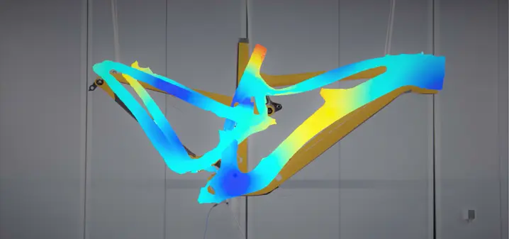
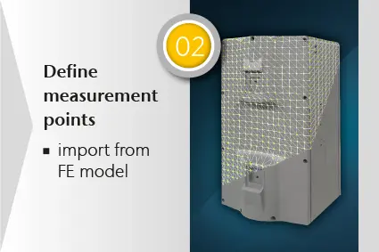
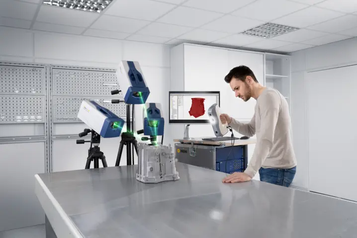
Typical test setup for the validation of FE simulation models
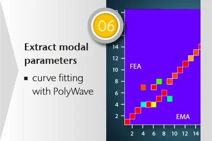
To perform an experimental vibration test as the counterpart of FE simulation models, the sample must be mounted and, of course, it must be excited to vibrate. This requires sample excitation in a specific manner covering the frequency range of interest and at specific locations. This approach may differ from numerical FE simulation, which only considers the inherent properties of a sample. It solves differential equation of motion for an assumed set of material properties and boundary conditions. Therefore, the results from an experiment are, strictly speaking, only the responses of the sample to a particular kind of excitation and with a specific mounting. Modes are extracted from the experimental results by a curve fitting procedure, which is part of the post-processing.
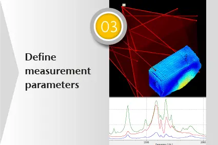
FE model validation based on Scanning Laser Doppler Vibrometry
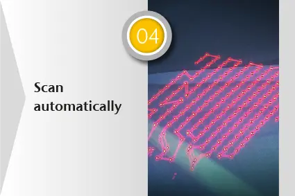
Can I trust the experiment? When defining the modal test setup the FE model’s boundary conditions should be replicated to allow comparison of Finite Element and measurement results. The measurement parameters like frequency bandwidth and the selected measurement points need to match the task. Mass-loading or stiffening effects should be avoided or taken into account during the modelling process. Using light as a sensor makes data from laser scanning vibrometers a more valid input for the model validation process. The laser method provides an exceptional high spatial measurement resolution since the sensor is software-defined and the sample is scanned automatically. The animated 2D/3D deflection shapes provide an intuitive visualization. This also helps reduce remaining ambiguities in the following validation and evaluation process. The resulting more sample points allows for a better curve fitting in the post-processing, improving identification of local parameter deviations such as local damping or locals changes in mass distribution.
Phase de développement du produit
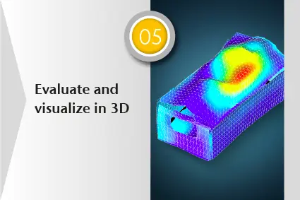

FE correlation with simulation modes: Frequency, damping and MAC
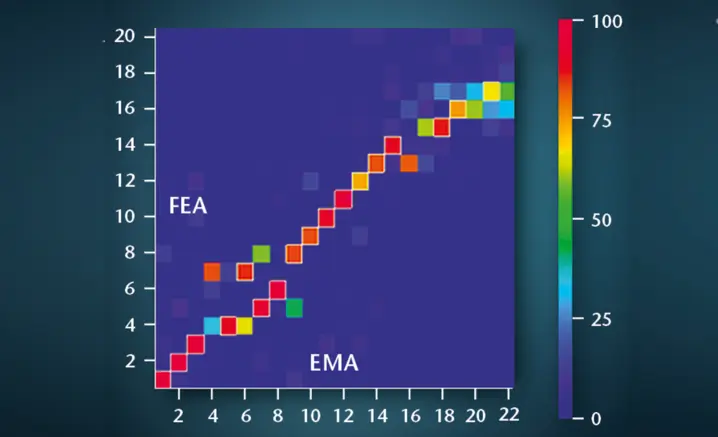
There are two parameters for comparing FE model and experiment: The eigenvalues and the eigenvectors as a result of solving the differential equations of motion in the model. They correspond to the resonance frequencies and mode shapes of an experimental test. The simplest approach is comparing the frequencies on one side and compare the eigenvectors and mode shapes visually. Using the modal assurance criterion MAC to compare the mode shapes is a common way to get and obtain an objective and quantitative comparison. The MAC requires modal modes rather than operational deflection shapes (ODS) as an input. These are extracted from the experimental results by a curve fitting procedure, which is part of the post-processing.

Parlez à nos experts
Nos experts sont prêts à vous aider dans vos projets grâce à des solutions de mesure sur mesure ou à vous aider à mesurer ce qui compte vraiment. Contactez-nous dès aujourd'hui.
Why validate simulated FE models with laser vibrometry
For simple samples, like cast metal plates, today’s FE models will predict the vibration modes and resonance frequencies very exactly if the finite elements are chosen in a reasonable way. Things are different when components and modelled structures become more complex. As soon as there are multiple parts, connected to each other by joints, or if they are made of composite material, the simulation results may be a lot less trustful at first shot. Therefore, these FE models need to be checked against real experimental data. If they can predict the experimental data correctly over the range of needed working conditions, the model is called validated. So for most real cases, finite element models need to be checked against experimental data to have a validated model, one that can be trusted and that can then subsequently be used to predict behavior under load or with small modifications. If the model does not fit experimental reality, there is no sense in using it for design purposes.
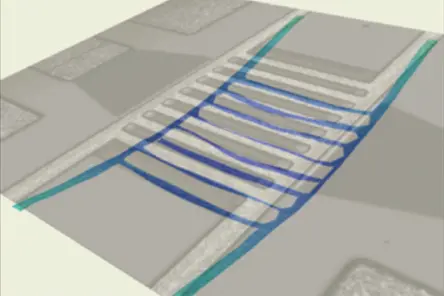
MEMS & microstructures: How laser vibrometry helps validate FE models
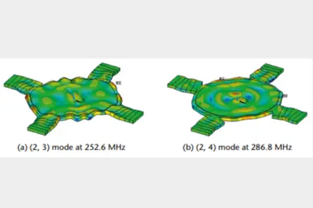
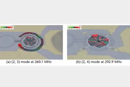
MEMS transducers are employed in many everyday objects from tire pressure sensors to mobile phones. Computer simulation models are essential to the development of MEMS devices, but need to be validated and refined through comparisons with precise experimental data. These validation data characterizing the real, physical mechanical response of a MEMS are easily acquired by laser-based Micro System Analyzers and optionally a wafer probe station.
Mechanical resonance is one of the most fundamental dynamics exhibited by MEMS. It is used for gyroscopes, mass sensors, optical scanners, clock oscillators etc. One natural research direction for MEMS resonators is to pursue higher resonance frequencies and find new applications. Electrostatic and piezoelectric transductions are two major driving principles. Both types can be measured even at highest frequencies, using laser vibrometers with light as a reliable precision sensor.
Testing services & application support for validating FE models
For further information, find these additional sites and learn about Polytec solutions for importing, measuring, comparing, evaluating, post-processing and documenting any modal test data.
- How does the non-contact technology of laser Doppler vibrometry work?
- How to perform laser scanning measurements in 2D or 3D?
Our PolyXperts are looking forward to hearing from you. For complex shaped and larger structures, automated testing with robotics can significantly reduce testing time and cost. Polytec operates several structural test centers around the globe – in Waldbronn Germany, Plymouth, MI USA and Yokohama Japan for measurements as a service. Contact Polytec for individual support or contact us and send your sample for cost-effective validation of your FE simulation models.
Polytec Magazine

Keep healthy teeth with ultrasonic scaler using EMS Piezon NO-PAIN technology
In order to keep your natural teeth as long as possible and to prevent caries and periodontal infections, home-care methods like brushing your teeth and flossing are essential. Unfortunately, these alone a…

On self-supporting and self-aligning compact shakers
Artificial excitation is the basis for various noise and vibration techniques, from experimental modal analysis, over transfer path analysis, load identification, simulation model correlation, hybrid model…
Laser-Doppler-Vibrometer set standards in the development of electric drives
Electric machines are increasingly being used as the primary drive technology in vehicles. The acoustic behavior of the drive is a key factor in the perceived quality of electric vehicles. Numerical method…

Pas de budget ? Mesurez tout simplement.
Que vous ayez besoin de prestations de mesure, de location d’équipement ou de leasing sur mesure, notre offre de service PolyFlex répond à vos objectifs techniques tout en s’alignant sur votre stratégie financière. Idéal pour les projets de courte durée, les besoins ponctuels ou les budgets limités.
Avec PolyFlex, vous obtenez des résultats sans compromettre vos délais ni votre budget.
Related products
VibroScan QTec Xtra
Le VibroScan QTec Xtra mesure les vibrations d'une manière innovante - sans contact, sur champ complet et avec une précision inédite. Grâce à sa révolutionnaire interférométrie multi-chemins, QTec® établit de nouvelles normes en matière de sensibilité optique et d'immunité aux interférences. Le Xtra, basé sur un laser infrarouge (SWIR), se distingue par la plus haute sensibilité optique pour garantir des mesures extrêmement précises, même sur des surfaces techniques exigeantes. Le VibroScan QTec Xtra assure une portabilité maximale grâce à l'acquisition de données intégrée et au générateur de signaux jusqu'à 32 MHz.
VibroScan QTec Xtra 3D
VibroScan QTec Xtra 3D mesure les vibrations de manière triaxiale selon une nouvelle méthode : sans contact, sur tout le champ et avec une précision sans précédent. Grâce à son interférométrie multipath révolutionnaire, QTec® établit de nouvelles normes en matière de sensibilité optique et d'immunité aux interférences. Le Xtra, basé sur un laser infrarouge (SWIR), se caractérise par une sensibilité optique maximale qui garantit des mesures très précises, même sur des surfaces techniques exigeantes. VibroScan QTec Xtra 3D assure une portabilité maximale grâce à l'acquisition de données intégrée et à un générateur de signaux jusqu'à 32 MHz.
RoboVib Station d'Essai Robotisée
En combinant un vibromètre à balayage 3D avec un robot industriel, le RoboVib® vous propose une station de mesure automatisée pour de la mesure de composants complexes jusqu'à l'intégralité des carrosseries de véhicule. Réduisez considérablement la durée et les coûts des essais, ainsi que les délais de commercialisation, dans le cadre de l'analyse modale expérimentale. Réalisez des essais complets à 360° sur la carrosserie d'un véhicule, par exemple, en un ou deux jours seulement et en une nuit, au lieu de plusieurs semaines de préparation avec les montages d'essai classiques.
Analyseur de microstructures MSA-600
Système de mesure tout-en-un pour la caractérisation 3D statique et dynamique des MEMS et des microstructures - maintenant jusqu'à 8 GHz. Le MSA-600 améliore les processus de développement et de contrôle qualité. Intégré aux stations sous pointes disponibles dans le commerce, il permet des tests au niveau des wafer.