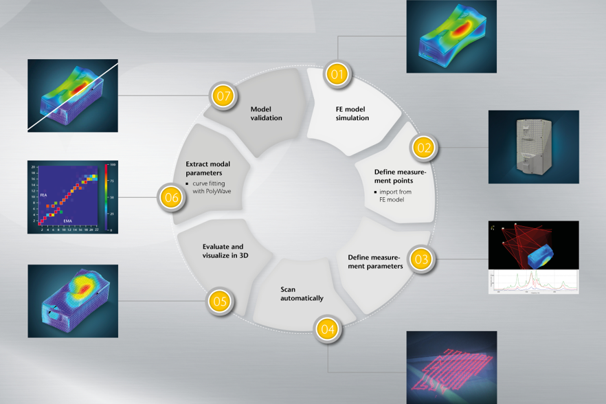
FEモデルの検証 - シミュレーションモデルと実験モーダル解析結果との比較
有限要素 (FE) モデルは、プロトタイプ作成の手間を省いてコンピュータ上で実行できるため、開発時間とコストを大幅に削減できます。ただし、これらの FE モデルが「実際の」デバイスの動作を予測することができるものか? という重要な問題があります。FEM 検証という用語の具体的な意味合いは、シミュレーションの結果を実際の実験(例えば実験モーダル解析など) データと比較することです。実際のケースでは、信頼できる検証済みモデルを取得するために、FE モデルを実験データと比較することが必要です。検証済みモデルを用いて、負荷がかかったときや小さな変更を加えたときの動作を予測することが重要です。もしモデルが実験データに適合しない場合、設計目的でそのモデルを使用する事はリスクを伴います。
FEシミュレーションモデル検証のための一般的な実験セットアップ
FEシミュレーションモデル検証用に振動テストを行う場合、サンプルを何等かの方法で支持した状態で、サンプル自体を振動させる必要があります。そのためには、サンプルの特定部位において、対象としている周波数範囲を励振できる加振方法が必要です。外部加振を用いることは、サンプルの固有周波数に着目した数値シミュレーションとは異なるアプローチとなります。一般的な固有値解析では想定される一連の材料特性と境界条件について微分運動方程式を解きます。これに対して加振実験の結果は、厳密に言えば、特定の種類の励振と特定の支持条件におけるサンプルの応答です。モードは、後処理の一部である曲線フィッティングによって実験結果から抽出されます。


 and MAC analysis and FE correlation")

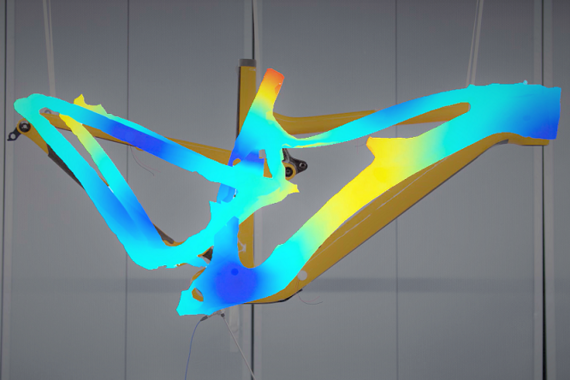
スキャニングレーザドップラ振動測定に基づくFEモデル検証
モーダル試験を行うにあたっては、有限要素と測定結果を比較できるように FE モデルの境界条件を極力再現するよう試みます。周波数帯域や選択した測定ポイントなどの測定パラメータも、検証する中で一致させておく必要があります。さらに質量負荷または剛性効果をどう扱うか考慮する必要も出てきます。光をセンサとして使用する、スキャニングレーザドップラ振動計は非接触、無負荷の状態で測定ができ、モデル検証プロセスに対するより有効なデータを提供します。スキャニング方式は、レーザがソフトウェア上で定義したサンプル表面の測定点を自動的にスキャンします。これにより非常に高い空間測定分解能を実現できるため、測定点数を接触式センサと比較して格段に増やす事ができ、後処理時のカーブフィッティングが向上し、局所的な減衰や質量分布の変化などの局所的なパラメータ偏差の識別が改善されます。また、アニメーション化された 2D/3D のたわみ形状により、直感的で分かりやすい可視化を瞬時に行えます。これにより、次ステップでの詳細検証および評価プロセスにおける曖昧さも軽減されます。
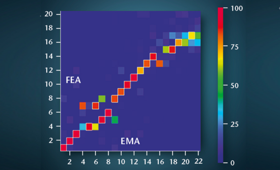
実験モード解析を用いたFEコリレーション: 周波数、減衰、MAC
FEモデルと実験結果を比較するためのパラメーターは主に 2つあります。モデル内の微分運動方程式を解いた結果として得られる固有値と固有ベクトルです。これらは、実験結果の共振周波数とモード形状に対応します。最も簡単な方法は、一方の周波数を比較し、固有ベクトルとモード形状を視覚的に比較することです。MAC(modal assurance criterion) を使用してモード形状を比較することは、客観的で定量的な比較を行う一般的な方法です。MAC では、入力としてたわみ形状 (ODS) ではなく、モーダルモードが必要です。これらは、後処理の一部であるカーブフィッティングによって実験結果から抽出されます。
FEモデル検証のためのスキャニングレーザドップラ振動計のレンタル、計測サービス
ビデオ: FEシミュレーションモデルをレーザドップラ振動計で検証する理由
鋳造金属板などの単純なサンプルの場合、有限要素が適切に選択されていれば、今日の FE モデルは振動モードと共振周波数を非常に正確に予測します。しかしながらコンポーネントやモデル化された構造がより複雑になると状況は変わります。複数のパーツがジョイントで互いに接続されていたり、複合材料で作られていたりすると、シミュレーション結果は最初は信頼性が低くなる可能性があります。したがって、これらの FE モデルは実際の実験データと照合する必要があります。必要な動作条件の範囲で実験データを正しく予測できる場合、モデルは検証済みと呼ばれます。したがって、検証済みモデルを用いて、負荷がかかったときや小さな変更を加えたときの動作を予測することが重要です。もしモデルが実験データに適合しない場合、設計目的でそのモデルを使用する事はリスクを伴います。


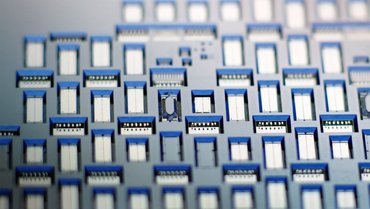
MEMS とマイクロシステム: レーザドップラ振動計がFEモデルの検証にどのように役立つか
MEMSトランスデューサは、タイヤ圧力センサから携帯電話まで、身近に多く使用されています。コンピュータシミュレーションモデルは MEMSデバイスの開発に不可欠ですが、正確な実験データとの比較を通じて検証および改良する必要があります。MEMSの実際の物理的機械的応答を特徴付ける、これらの検証データはレーザドップラ振動計ベースのマイクロ システムアナライザによって簡単に取得できます。
機械共振は、MEMSが持つ最も基本的なダイナミクスの 1 つです。ジャイロスコープ、質量センサ、光スキャナ、クロック発振器などに使用されています。MEMS共振器の一般的な方向性としては、より高い共振周波数を追求し、新しい用途を見つけることです。静電変換と圧電変換は2つの主要な駆動原理です。どちらのタイプも信頼性の高い高精度センサーとして、光を使用するレーザドップラ振動計を使用して、高周波領域でも測定することができます。

FEモデルを検証するための計測サービスとアプリケーションサポート
レーザドップラ振動計の非接触技術は何に有効? 2Dまたは3Dでレーザスキャン測定を実行する方法は? 当社の エンジニアは、皆様からのご連絡をお待ちしております。ポリテックでは、ドイツのヴァルトブロン、米国ミシガン州プリマス、日本の新横浜にサービス拠点があります。サービスについての詳細を知りたい場合は是非お問い合わせください。FE シミュレーションモデルの検証のためにサンプル計測を行う事も相談可能です。
レーザドップラ振動計によるFEモデル検証のデモ相談はこちらをクリック
ポリテック マガジン
歯科衛生機器の改善
EMS Piezon NO-PAINテクノロジーを採用した超音波スケーラ
加振力
自立型および自己整合型コンパクトシェーカー
静寂
振動特性の精密な分析
購入しなくても測定できます
計測サービス、機器レンタル、リースなど、ポリテックは設備投資以外の選択肢も用意しております。短期間プロジェクト、一時的なご利用、あるいはご予算に限りがある場合でも、ぜひお問い合わせください。お客様の具体的なニーズに合った最適なソリューションを共に見つけさせていただきます。
関連製品

VibroScan QTec Xtra
VibroScan QTec Xtraは、振動を非接触、全視野、前例のない精度で測定する新しいソリューションです。画期的なマルチパス干渉計を備えたQTec® は、光学感度と干渉耐性の点で新しいスタンダードを確立しました。赤外線 (SWIR) レーザーをベースとするXtra は、最高の光学感度を特徴としており、要求の厳しい技術的表面でも高精度の測定を保証します。VibroScan QTec Xtraは、最大32MHzの信号発生器を内蔵しつつも、統合されたデータ取得により最大限の携帯性を保証します。

VibroScan QTec Xtra 3D
VibroScan QTec Xtra 3Dは、非接触、全視野、高精度で三軸振動測定ができる新しいソリューションです。画期的なマルチパス干渉計を備えたQTec® は、光学感度と干渉耐性の点で新しいスタンダードを確立しました。赤外線 (SWIR) レーザーをベースとするXtra は、最高の光学感度を特徴としており、要求の厳しい技術的表面でも高精度の測定を保証します。VibroScan QTec Xtra 3Dは、最大32MHzの信号発生器を内蔵しつつも、統合されたデータ取得により最大限の携帯性を保証します。
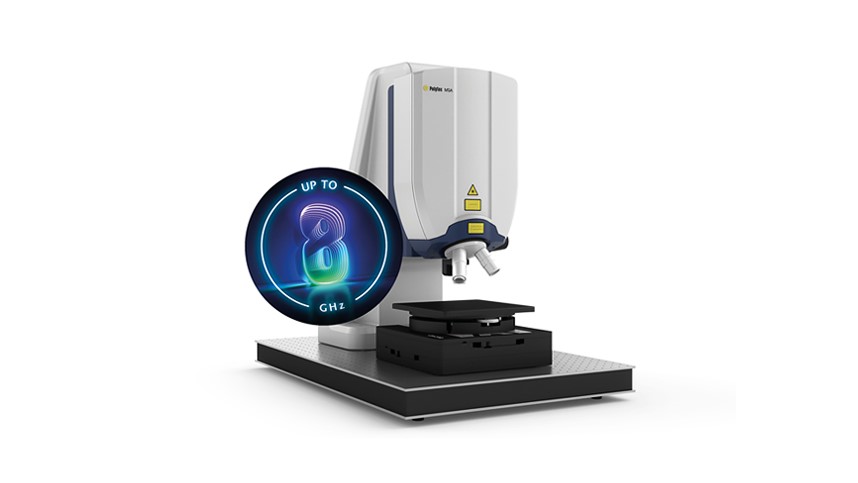
マイクロシステムアナライザ MSA-600
MSA-600 は、MEMS や微細構造の静的・動的な 3D 特性を測定するオールインワン光学測定ソリュー ションで、最大 8GHz まで対応します。MSA-600は、マイクロシステム開発および品質検査を強化し、市販のプローブステーションに組み込むことにより、ウェーハレベルでのテストも可能にします。

マイクロシステムアナライザ MSA-100-3D
3Dマイクロシステムアナライザは、3つの空間方向の振動成分を一度に測定します。この光学計測システムは、面内および面外の振動成分について、サブピコメータレンジの振幅分解能で、DCから25 MHzまでの高分解能3次元振動解析を可能にします。

全自動非接触振動測定システム RoboVib®
RoboVib® は、3D スキャニングレーザドップラ振動計と産業用ロボットを組み合わせた自動テストステーションです。実験モード解析では、試験時間と費用を大幅に削減し、市場投入までの時間を短縮できます。例えば、車体の 360° の総合的な試験を、従来の試験セットアップでは数週間かかっていた測定を、わずか 1 〜 2 日、または一晩で実施できます。

計測/レンタルサービス
当社の計測サービスは、幅広いアプリケーションに対応しており、お客様サイトまたは当社のオフィスにおいて、最近ではオンライン対応も徐々にスタートしております。各アプリケーションに最適なレーザドップラ振動計をお貸出しするレンタルサービスや、経験豊富なアプリケーションエンジニアが、お客様のプロジェクトを個別にサポートし、測定を行います。