Finite Element model validation - comparing simulation model & modal test data
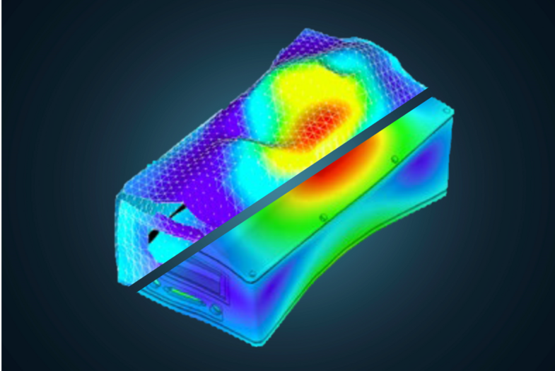
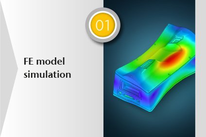
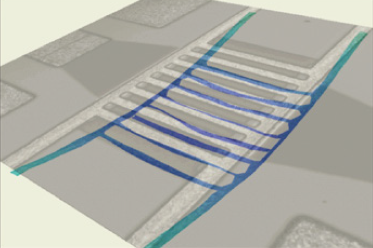
Finite Element (FE) models can greatly reduce development time and cost, as it can be done on a computer with less prototyping. But the main concern is that these FE models have to predict the behavior of the « real » device. The idea behind the term FEM validation is to compare the results from a simulation to data from a real test, the so-called experimental modal test. For most real cases, FE models need to be checked against experimental data to obtain a validated model, that can be trusted and then be used to predict behavior under load or with small modifications. If the model does not fit the experimental reality, there is no point in using it for design purposes.
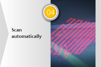
Validate FE models based on real measurement data by scanning laser Doppler vibrometry (SLDV):
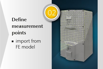
- Rely on full-field and non-contact data with FEM like spatial resolution
- Measure exactly on node points, no interpolation of data points needed
- Master challenging assemblies, especially with glued, screwed and bonded joints
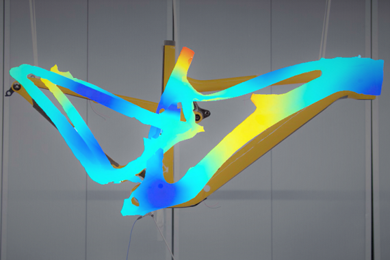
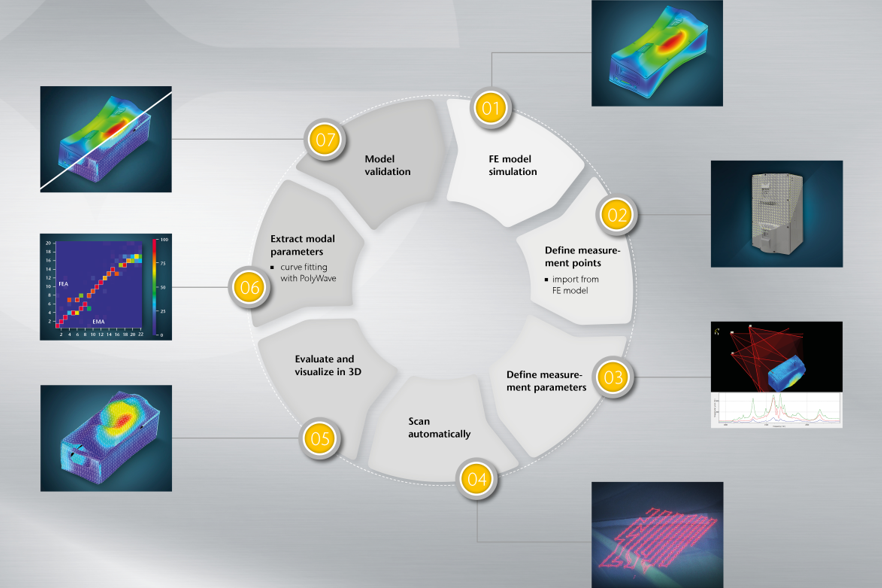
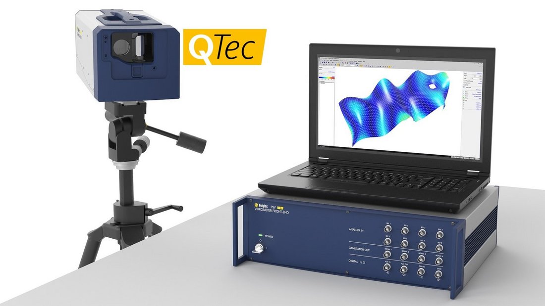
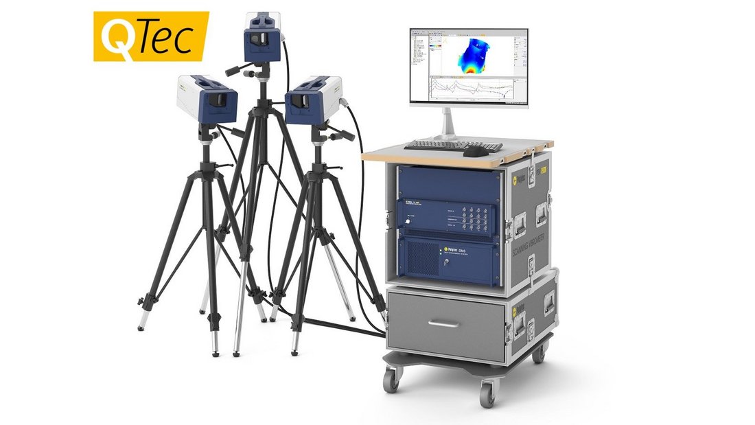
Typical test setup for the validation of FE simulation models
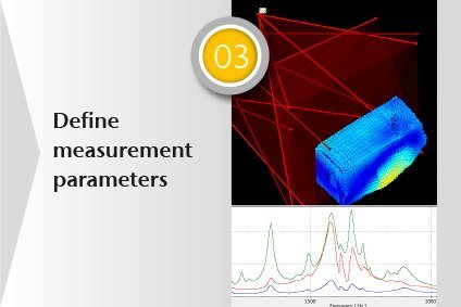
To perform an experimental vibration test as the counterpart of FE simulation models, the sample must be mounted and, of course, it must be excited to vibrate. This requires sample excitation in a specific manner covering the frequency range of interest and at specific locations. This approach may differ from numerical FE simulation, which only considers the inherent properties of a sample. It solves differential equation of motion for an assumed set of material properties and boundary conditions. Therefore, the results from an experiment are, strictly speaking, only the responses of the sample to a particular kind of excitation and with a specific mounting. Modes are extracted from the experimental results by a curve fitting procedure, which is part of the post-processing.
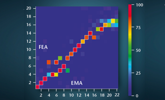
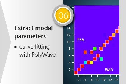
FE correlation with simulation modes: Frequency, damping and MAC
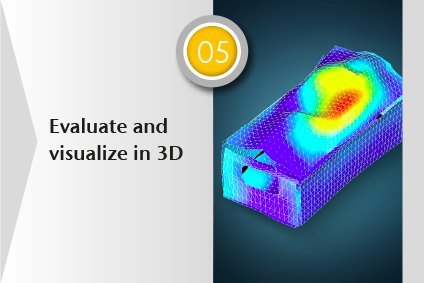
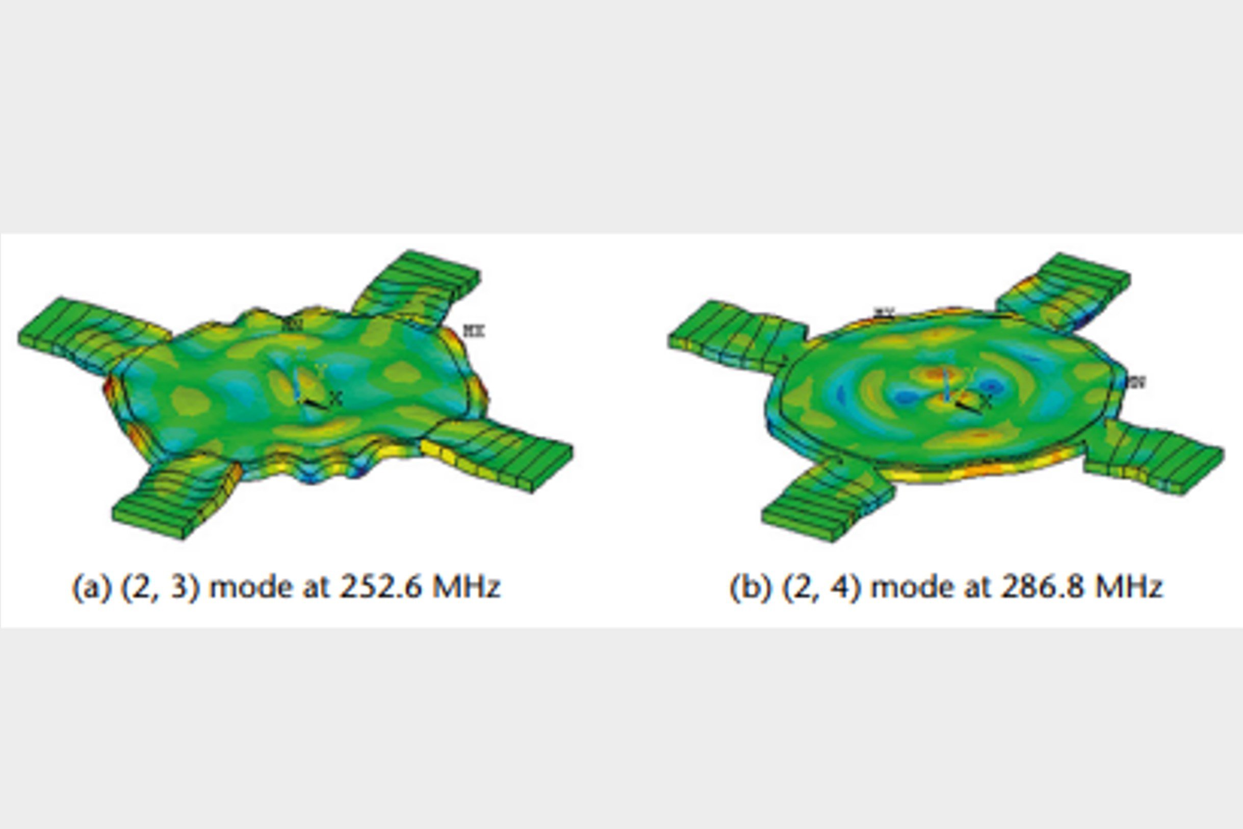
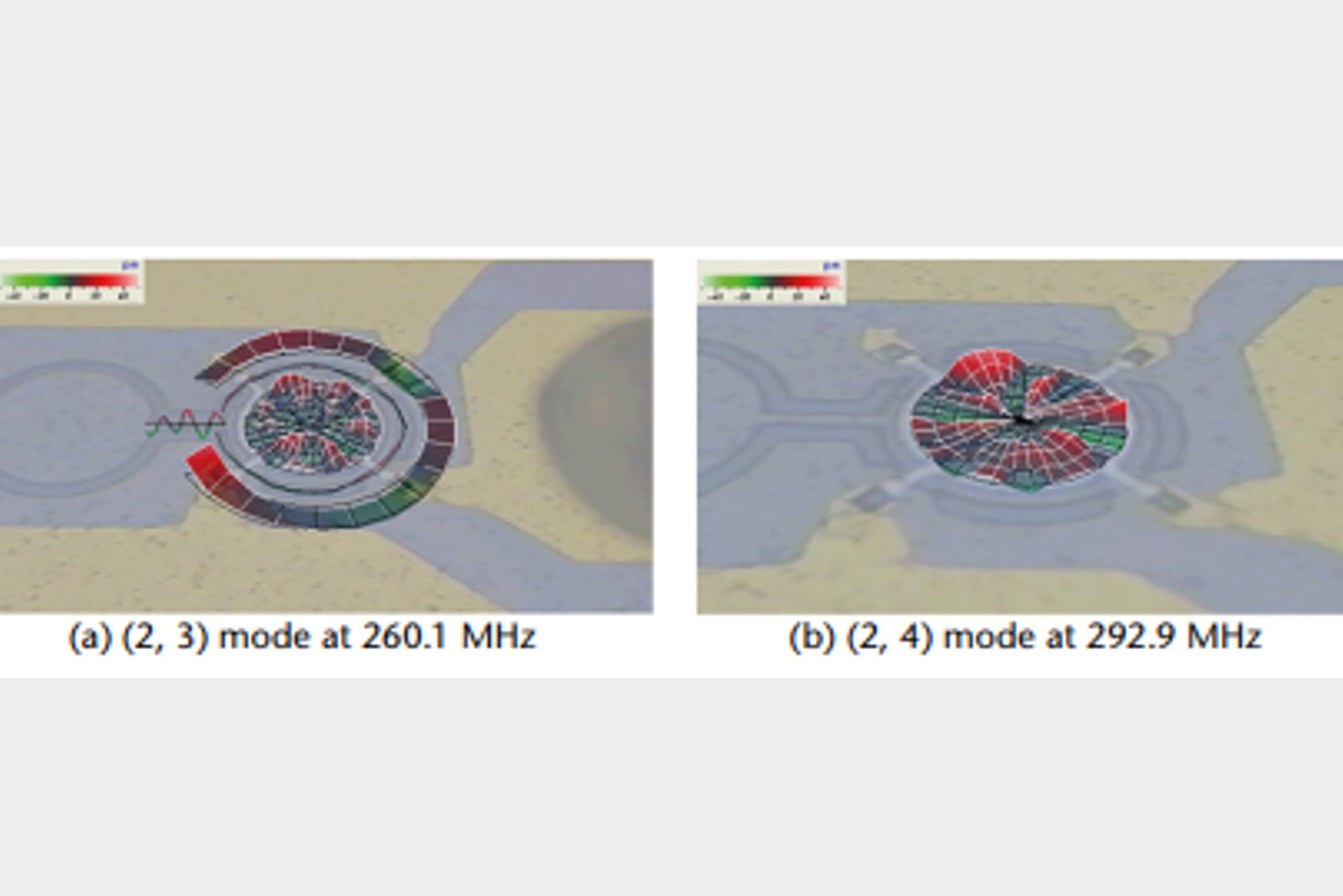
There are two parameters for comparing FE model and experiment: The eigenvalues and the eigenvectors as a result of solving the differential equations of motion in the model. They correspond to the resonance frequencies and mode shapes of an experimental test. The simplest approach is comparing the frequencies on one side and compare the eigenvectors and mode shapes visually. Using the modal assurance criterion MAC to compare the mode shapes is a common way to get and obtain an objective and quantitative comparison. The MAC requires modal modes rather than operational deflection shapes (ODS) as an input. These are extracted from the experimental results by a curve fitting procedure, which is part of the post-processing.
Speed up your FE model validation process, using our rental, labs & testing services
Video: Why validate simulated FE models with laser vibrometry
For simple samples, like cast metal plates, today’s FE models will predict the vibration modes and resonance frequencies very exactly if the finite elements are chosen in a reasonable way. Things are different when components and modelled structures become more complex. As soon as there are multiple parts, connected to each other by joints, or if they are made of composite material, the simulation results may be a lot less trustful at first shot. Therefore, these FE models need to be checked against real experimental data. If they can predict the experimental data correctly over the range of needed working conditions, the model is called validated. So for most real cases, finite element models need to be checked against experimental data to have a validated model, one that can be trusted and that can then subsequently be used to predict behavior under load or with small modifications. If the model does not fit experimental reality, there is no sense in using it for design purposes.
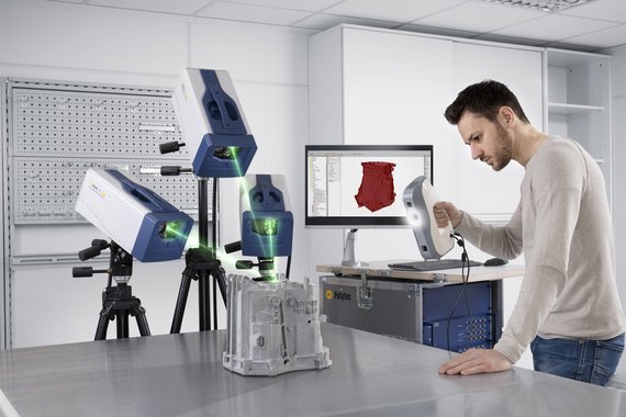
Testing services & application support for validating FE models
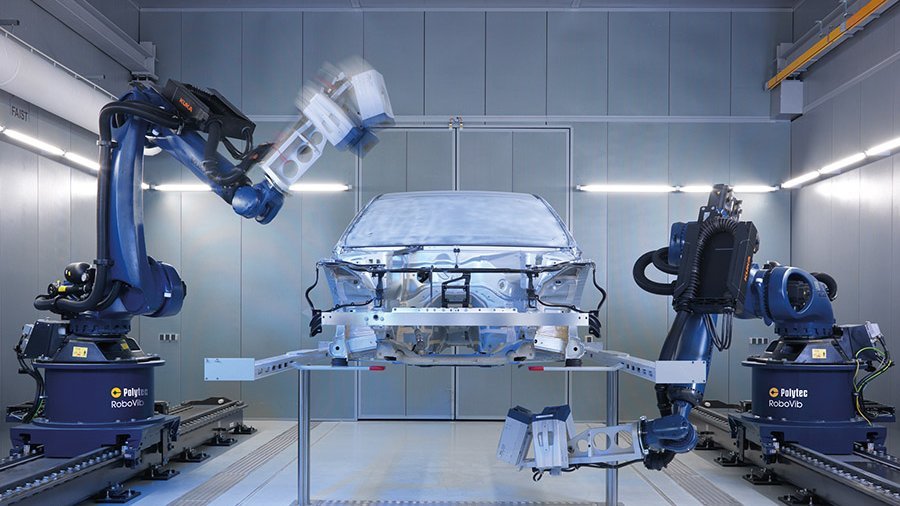
For further information, find these additional sites and learn about Polytec solutions for importing, measuring, comparing, evaluating, post-processing and documenting any modal test data. How does the non-contact technology of laser Doppler vibrometry work? How to perform laser scanning measurements in 2D or 3D? Our PolyXperts are looking forward to hearing from you. For complex shaped and larger structures, automated testing with robotics can significantly reduce testing time and cost. Polytec operates several structural test centers around the globe – in Waldbronn Germany, Plymouth, MI USA and Yokohama Japan for measurements as a service. Contact Polytec for individual support or contact us and send your sample for cost-effective validation of your FE simulation models.
Free demo on how to validate your FE simulation models with laser measurement data
Polytec Magazine
Improving dental healthcare
Keep healthy teeth with ultrasonic scaler using EMS Piezon NO-PAIN technology
Exciting forces
on self-supporting and self-aligning compact shakers
Incredibly quiet
thanks to precise analysis of vibration characteristics
No budget? Just measure.
Whether you need contract measurements, equipment rental, or leasing, our scalable services deliver precise data—without the overhead of major investments. Ideal for short-term projects, occasional use, or limited budgets. Get in touch with us—together we will find the right solution for your specific needs!
