なぜ表面の平坦度を測定するのか?
技術部品の機能性を確保するためには、多くの用途で平坦度が重要であるため、表面平坦度の許容差は多くの製造部品で定義されています。平坦度は本質的な表面パラメータであり、例えばフランジやバルブシートのシール面の漏れに影響します。光学研磨が適用される精密光学では、ガラス基板、光学ミラー、ビームスプリッターなどの平坦度は、最も重要な品質指標のひとつです。
しかし、平面度公差が広く使われているのは、精密機械や光学部品だけではありません。エレクトロニクス産業では、はんだ付けプロセスなどで複数の部品を取り付ける際、電気的接続性を確保するために、プリント基板の平面度が規定の許容範囲内にあるかどうかを知ることが重要です。互いに相対的に動く表面の場合、表面の平坦度は部品のノイズレベルや放音にも影響します。簡単に言えば、平坦度の許容差は、製品の信頼性、機能性、さらにはノイズにまで広く影響します。
干渉計精度で表面の平坦度を評価
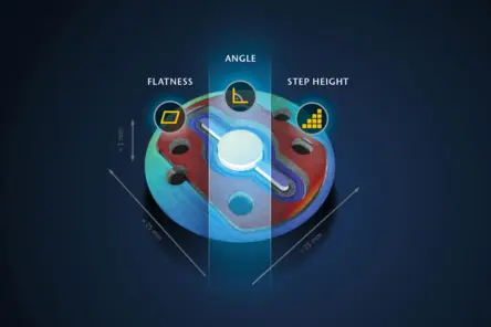
赤外分光器のキュベットは、高品質の光学的に透明な材料で構成された重要な部品であり、非常に精密な機械的固定具を使用したアセンブリ内での正確な位置決めが必要です。TopMap 白色光干渉計は、治具に対するウィンドウの位置と向き、治具の表面平坦度、キュベットの異なるレベル間の垂直方向の段差の高さなどの各パラメータを測定します。
TopMapはスキャニング白色光干渉計(WLI)であり、形状、段差、テクスチャーを非接触で特性評価し、視野に依存しない最高の垂直分解能を提供します。45mm×34mmを1ショットで測定できるこの光学式プロファイラーでは、つなぎ目がなくても、キュベット全体を1回の測定でわずか数秒で測定できます。専用の測定位置で機械的に表面に触れる触覚測定技術に比べ、キュベットの光学的全視野測定では、ほぼ100万個の測定点が含まれます。
ISOフラットネスとその計算方法
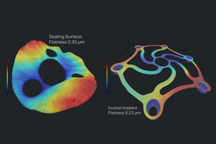
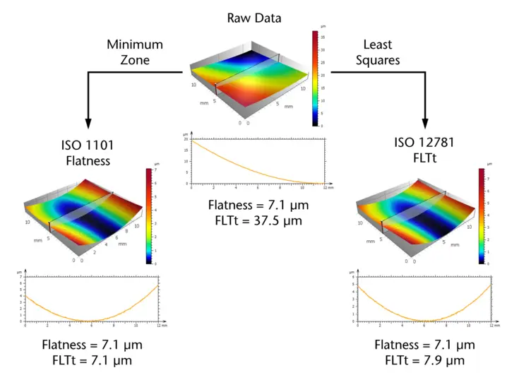
一般に、計測における幾何学的平坦度は、記録されたすべての測定点を通して2つの平行な平面の差として定義される。しかし、これらの平行面の計算方法が異なるさまざまなISO規格が利用可能です。異なる測定システムや技術で測定された表面平坦度の測定結果を比較するには、特定のISO規格を参照することが重要です。
ISO 1101規格では、2つの平行平面間の距離は、すべての測定点を含みながら可能な限り小さくなければならないと定義しています。
ISO 12781では、平坦度はより一般的に、2つの平面の最小点と最大点の間の距離として定義されています。使用するISO規格にかかわらず、単一のスパイクが測定結果を支配することを防ぐために、データセットの異常値を効果的に除去することが重要です。
面平坦度測定(光コヒーレンス・スキャニング)
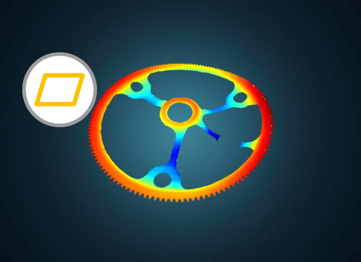
白色光干渉法を用いたコヒーレンススキャニング技術のような、面的で非接触な平坦度測定技術は、1ショットでサンプルエリア全体を確実にカバーします。瞬時に数百万点もの測定ポイントを取得できる光学式平面度測定は、
製造の初期段階で、不具合部品をNOK部品として検出することを可能にします。柔らかい部品や非常に薄い部品であっても、被測定面を変形させることなく非侵襲的に測定できるため、信頼性の高い平坦度評価が可能です。面平坦度測定は、品質管理や生産工程での全数検査に最適です。
光学式表面平坦度測定の利点
平坦度測定は通常、触覚式プロファイラまたは非接触式(光学式)のいずれかを用いて行われる。座標測定機(CMM)のような触覚測定システムは、大型部品の平坦度測定や、複数の寸法公差、幾何公差、位置公差を測定する場合によく使用されます。
しかし、CMMによる測定はポイント・バイ・ポイントの測定であるため、長時間を要することが多い。多くの場合、測定時間を短縮するために、より大きなポイント間隔が選択されます。しかし、この方法では、局所的な形状の偏差が見逃されることになります。
合否判定のための自動平面度公差チェック
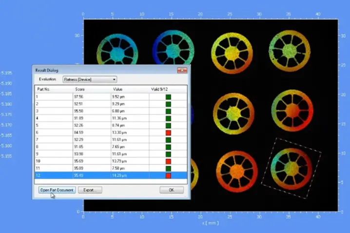
合格/不合格判定のための自動平坦度公差検査
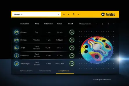
製造工程で生産されるすべての部品が、指定された平坦度公差に準拠し、品質基準に適合していることを保証するために、生産システムには100%の品質検査を行うための測定ルーチンが必要です。カスタムソフトウェアオプションにより、特定の検査ニーズやルーチン測定に適応し、シンプルな測定レシピを保存して実行することができます。平坦度の許容誤差を個別に設定し、測定値と即座に比較することで、合否結果が得られます。サンプルの設置位置のばらつきが検出され、自動パターン認識により、評価が自動的に新しい位置に適応されます。これにより、厳しい環境下でも高い再現性が保証されます。
関連製品
Pro.Surf+
Multi-sensor optical profiler combining large-area form measurement with integrated roughness analysis. Pro.Surf+ delivers fast, traceable form and roughness results in one production-ready system.
Pro.Surf
Pro.Surf is a telecentric WLI/CSI system for fast, non-contact form and topography measurement. Due to a large FoV it is perfect for wider parts and trays - down to nm scale.
Metro.Lab
Metro.Lab is a compact, wide-area bench-top surface profiler. It combines high measurement performance with a small footprint — ideal for space- or budget-conscious applications that still require reliable 3D surface data.
自信を持って最適な表面プロファイラーをお選びください - 「購入前に試用」アプローチのメリットを享受できます。

ご要望について専門家とご相談ください
まずは部品仕様、公差、ワークフローについて簡単に話し合いましょう。必要に応じて、実現可能性調査、PolyMeasure(契約測定)、またはPolyRentトライアルをオプションの次のステップとして追加することも可能です。